Use Boundary Diagrams to define inputs and outputs for your system

BOUNDARY DIAGRAM
OVERVIEW
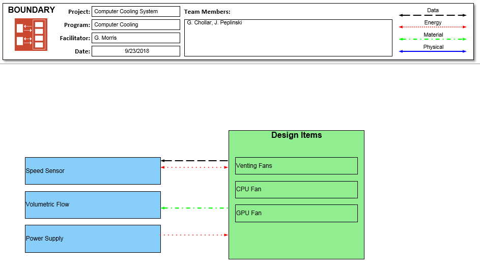
Boundary Diagrams are used to identify how systems, sub-systems, or components interact with one or more design items contained within a defined boundary. The direction and type of interactions can be defined. Boundary Diagrams are usually created before a FMEA session.
FEATURES
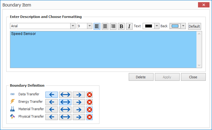
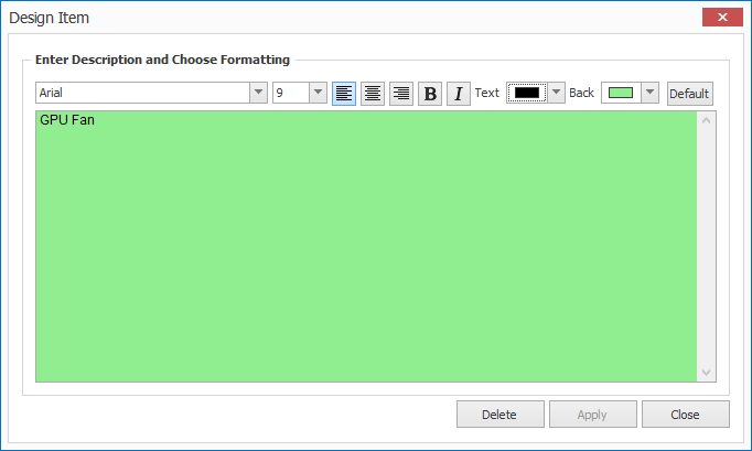
- Interactively create Boundary and Design Items
- Define four types of transfers: Data, Energy, Material, Physical
- Define transfer directions: input, output, and bi-directional
- Custom formatting of each item
BENEFITS
Boundary Diagrams can be used in product development processes to:
- Identify which systems, sub-systems, or components influence a product or process within the boundary of the team's responsibility.
- Illustrate elements outside the boundary of the team's responsibility that could be a potential cause and/or effect of failure.
REQUIREMENTS
- Microsoft Windows 7, 8, 10, 11
- Microsoft Excel 2016, 2019, 2021, 365
- WARNING: SDI Tools does not support these versions of Office 365 (Office from Microsoft Store, Office Online, Office for Mac, Office for iOS)
- Administrator rights required to install software
EXPORTING
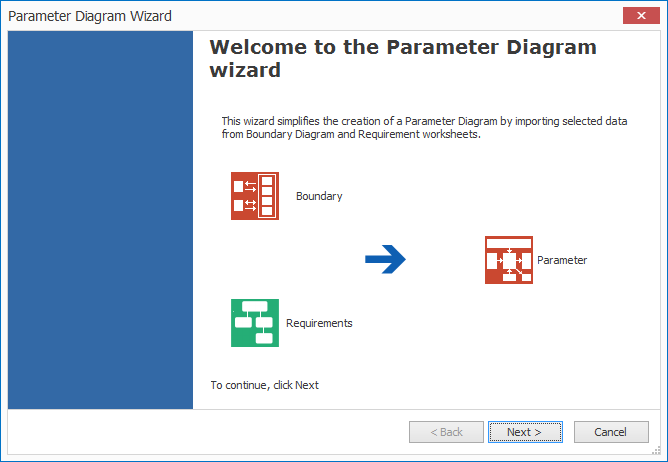
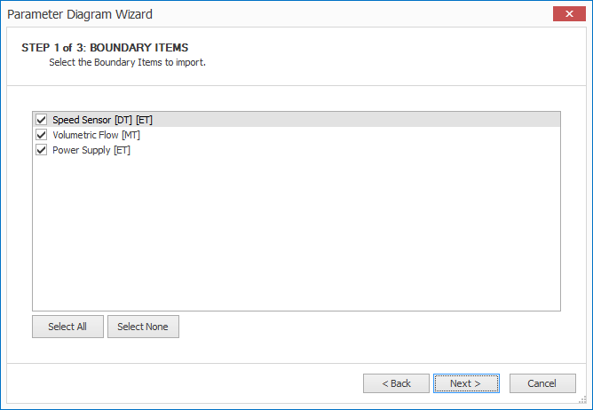
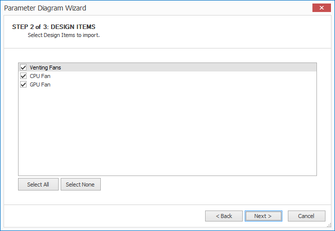
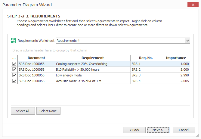
- Export to Parameter Diagram worksheet